Jib Crane Analysis
This project analyzed how moving trolley loads alter internal forces in a jib crane, translating structural theory into practical safety-driven engineering insight.
00

Problem
The jib crane in question is designed to support moving loads via a trolley system, presenting a critical scenario for internal force analysis in real-world structural engineering. When a load of 750 lb is suspended from the trolley, which travels along the top of the jib, it is necessary to understand how the crane’s members are internally stressed to ensure safety and proper function. Specifically, there is a need to determine the internal normal force, shear force, and bending moment in the jib at key locations (points C and D) for different positions of the load, as well as to calculate the support reactions at point A. Additional analysis is required to document how the internal forces and moments vary as the trolley, and thus the load, moves from an initial position 3 ft away from point G to a position 1 ft away from point B. This will provide comprehensive insight into the structural demands imposed by the mobile load and ensure safe and effective crane design and operation.
Solution
Overall, this report serves as a detailed and organized record of our analysis, documenting the structural demands imposed on the jib crane and validating the crane’s performance under the specified loading conditions. The integration of free-body diagrams, equilibrium equations, member-force breakdowns, and cut-section evaluations demonstrates a thorough and comprehensive approach to structural modeling. This work not only verifies that the crane can safely carry the applied load at the evaluated position but also reinforces the value of methodical engineering analysis in real-world design and evaluation scenarios.
The objective of this analysis was to determine the internal normal force, shear force, and bending moment in the jib-crane system as a function of the trolley location. To achieve this, we developed general equilibrium equations for each major member, BFG, BC, AED, and the entire crane, and applied these expressions at multiple discrete positions along the jib.
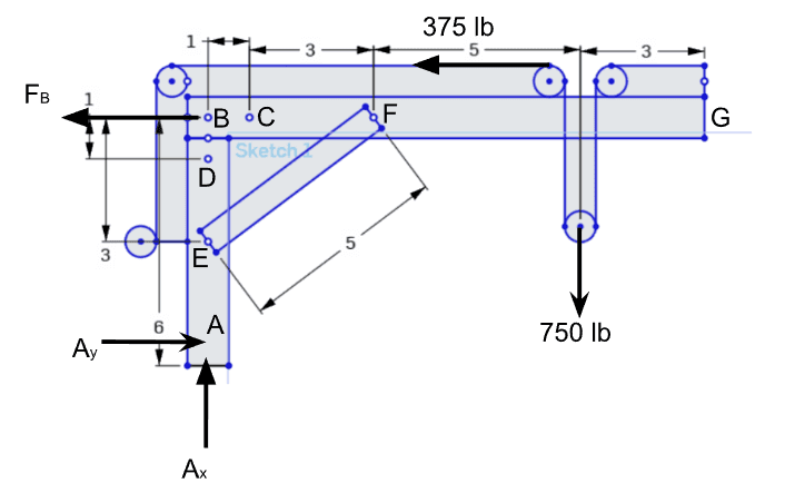
This project presents a comprehensive static analysis of a jib-crane system supporting a 750-lb load applied through a trolley mechanism. The objective was to determine the internal forces—normal force, shear force, and bending moment—within the jib and support column for a full range of trolley positions rather than at a single point. To accomplish this, the team developed generalized equilibrium equations for all critical internal force components, allowing evaluation at any position (x) along the jib. These generalized formulas were then applied across a sequence of discrete (x)-values (from 1 to 9), generating complete internal force profiles for the jib member (BFG), the column segment (AED), and the short segment (BC). Results were plotted in Excel to verify linearity, trends, and consistency with the theoretical expectations of statics.
We developed and used a customized Google Sheets workbook to compute the internal normal forces, shear forces, bending moments, and reaction forces for each x-position along the jib, allowing us to apply the general equilibrium equations systematically across the full 10-ft span (Moment Makers).
Year
2025
Timeframe
2 months
Tools
OnShape, Excel Spreadsheets
Category
Course Project
01

02

03

04

05

06

see also


